1.3.4 USR20 Positioning/Heading RTK Module
USR20-A Airborne Unit
Product Description
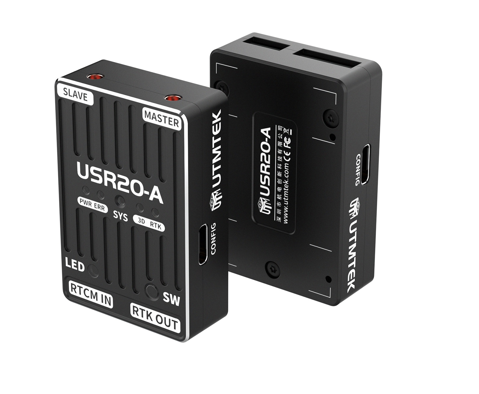
The USR20-A Positioning/Heading RTK Airborne Unit Module is a high-precision airborne positioning and heading core component specifically designed for UAVs. It supports full constellation multi-frequency GNSS signal reception, achieving centimeter-level RTK precise positioning and dual-antenna real-time heading calculation. It effectively replaces traditional magnetic compass and resists electromagnetic interference, providing stable and reliable position and heading data for the flight controller. The module uses an integrated Airborne Unit design with high integration and strong adaptability, supports high-speed data output and differential data link interaction. In inspection, surveying, security, and other scenarios, it continuously ensures high-precision hovering, precise route flying, and directional operations for UAVs.
Specifications
| Parameter | Specification |
|---|---|
| Operating Voltage | 5V |
| Operating Current | 350mA |
| Electronic Compass | 3 Axis |
| GNSS Navigation System | BDS B1I/B2I/B3I, GPS L1C/A/L2P(Y)/L2C/L5, GLONASS L1/L2, Galileo E1/E5a/E5b, QZSS L1/L2/L5 |
| Antenna Gain | 2.5 dBi |
| LNA Gain | 33±2dB |
| First Fix Time | Cold start ≤30s, Hot start ≤5s |
| RTK Initialization Time | ≤5 minute @2.0mCEP |
| Data Update Rate | 20Hz |
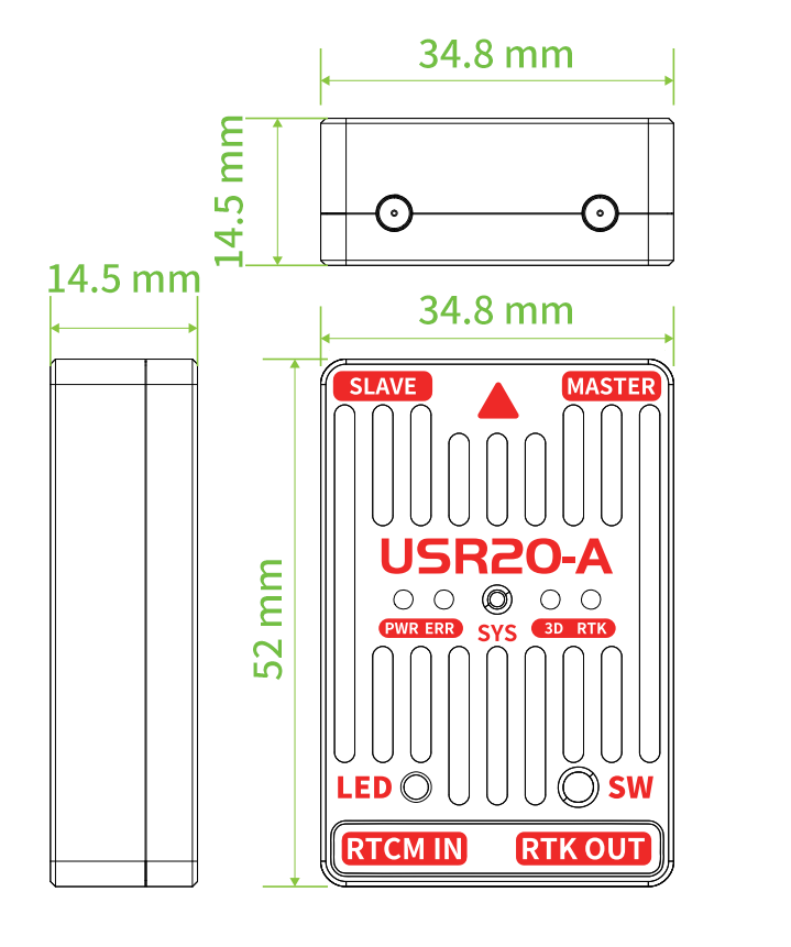
| Dimensions | 52mm × 34.8mm × 14.5mm |
| Weight | 30g |
| Operating Temperature | -20~80°C |
Interface Definition
| Interface Name | Function Description | Interface Type |
|---|---|---|
| CONFIG | Configuration interface | Type-C |
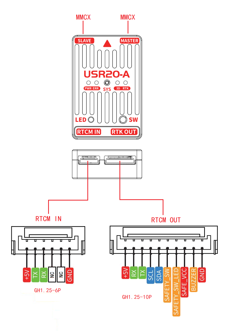
| RTCM IN | Differential signal input interface | GH1.25-6P |
| RTK OUT | Flight controller GPS1 interface | GH1.25-10P |
| MASTER | Main antenna interface (positioning) | MMCX |
| SLAVE | Secondary antenna interface (heading assist) | MMCX |
| SW | Safety button | - |
Status LEDs
| LED | Function |
|---|---|
| SYS | Flight controller working indicator |
| PWR | RTK power indicator |
| ERR | RTK error indicator |
| 3D | RTK enters 3D positioning mode |
| RTK | RTK enters FIX mode |
Product Drawings
USR20-A Interface Diagram
USR20-A Dimensions Diagram
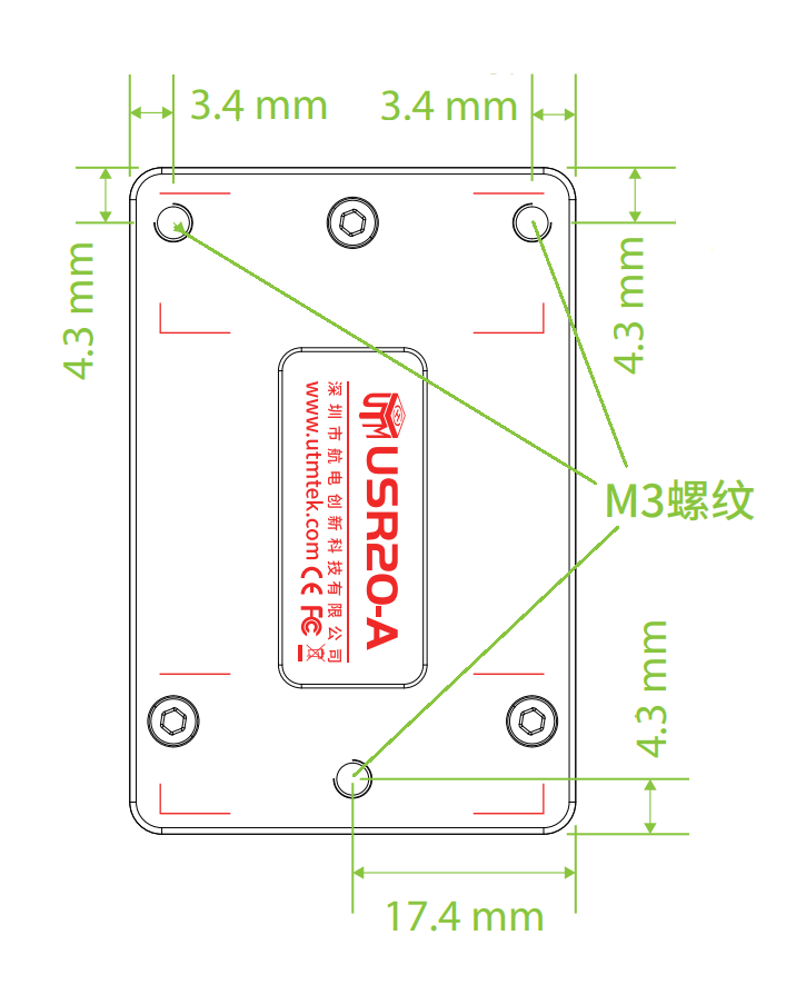
USR20-A Installation Diagram
USR20-G Ground Base Station
Product Description
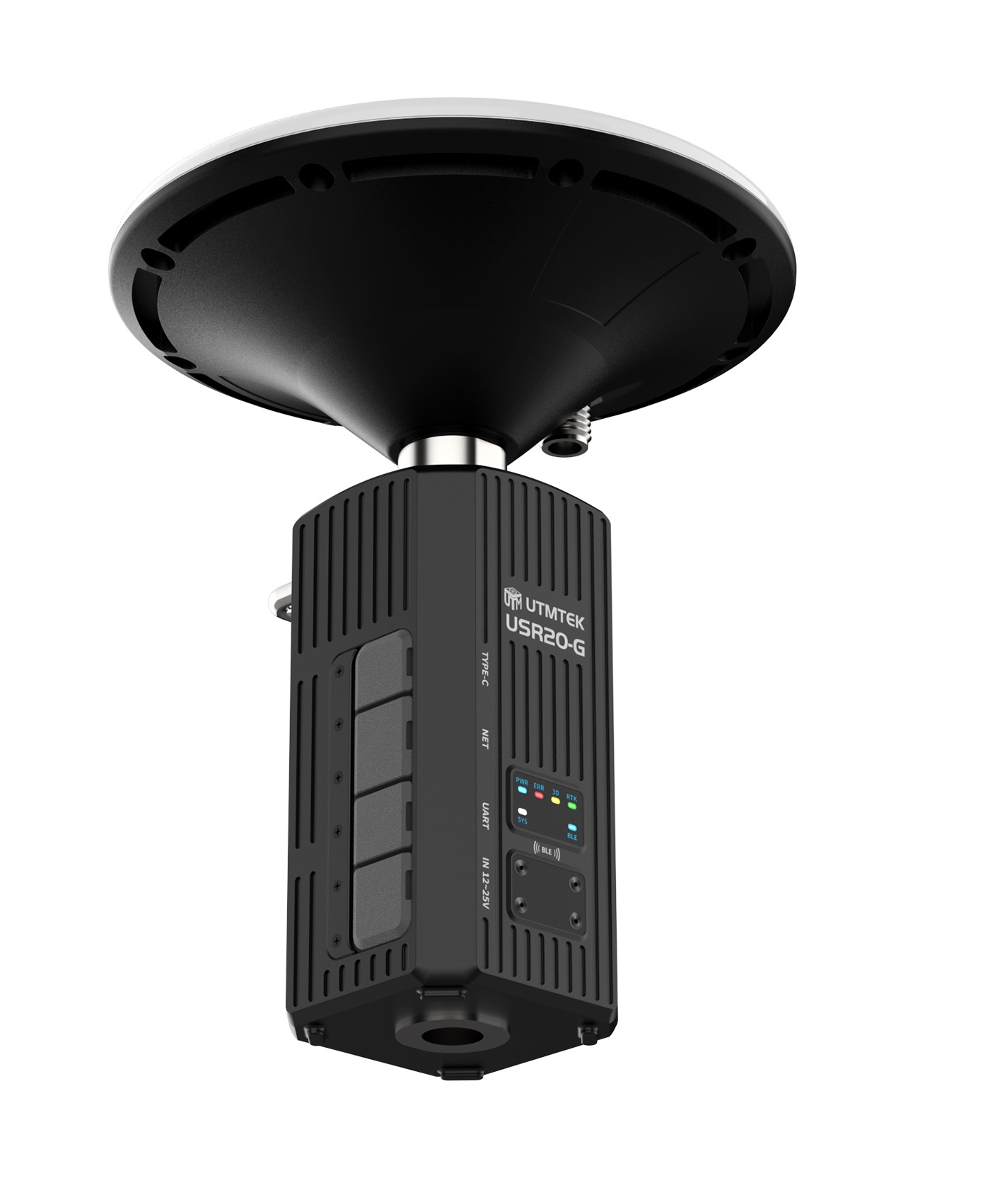
The USR20-G RTK Ground Base Station is a GNSS reference station installed on the ground with precisely known position. By real-time receiving satellite signals, it calculates ionospheric, tropospheric, orbital, and clock errors, and sends them to UAVs and other mobile terminals in the form of differential data, elevating them from ordinary meter-level positioning to centimeter-level high-precision positioning. This provides stable and reliable high-precision position reference for UAV aerial surveying, inspection, and autonomous operations.
Specifications
| Parameter | Specification |
|---|---|
| Operating Voltage | 12~25V |
| Operating Current | 350mA |
| IMU | ACC×3, GYRO×3 |
| GNSS Navigation System | BDS B1I/B2I/B3I, GPS L1C/A/L2P(Y)/L2C/L5, GLONASS L1/L2, Galileo E1/E5a/E5b, QZSS L1/L2/L5 |
| Antenna Gain | 5 dBi |
| LNA Gain | 38±2dB |
| First Fix Time | Cold start ≤30s, Hot start ≤5s |
| RTK Initialization Time | ≤5 minute @2.0mCEP |
| Data Update Rate | 20Hz |
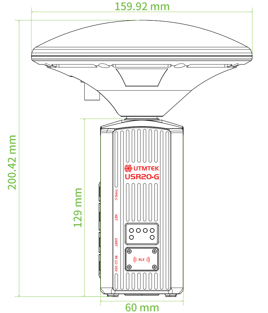
| Dimensions with Antenna | 200mm × 160mm × 160mm |
| Bluetooth Protocol | BLE5.0 / SPP2.1 |
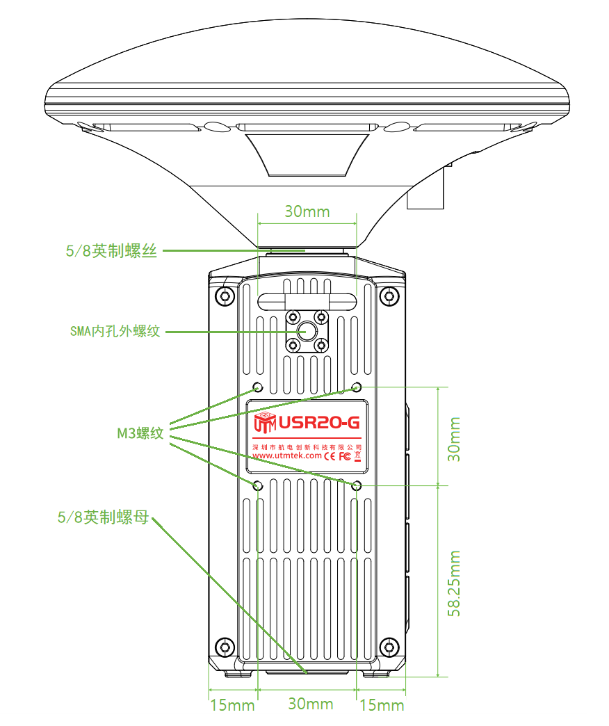
| Antenna Mounting | 5/8 inch thread |
| Base Station Mounting | 5/8 inch nut |
| Weight | 650g |
| Operating Temperature | -20~80°C |
Interface Definition
| Interface Name | Function Description | Interface Type |
|---|---|---|
| IN 12-25V | Power interface | XT30 |
| UART | Differential data output serial port | MR30 |
| NET | Differential data output network port | RJ45 |
| TYPE-C | Configuration interface USB2.0 | Type-C |
| Antenna Interface | SMA female inner thread | - |
Status LEDs
| LED | Function |
|---|---|
| BLE | Bluetooth connection indicator |
| SYS | System working indicator |
| PWR | RTK power indicator |
| ERR | RTK error indicator |
| 3D | RTK enters 3D positioning mode |
| RTK | RTK enters FIX mode |
Product Drawings
USR20-G Dimensions Diagram
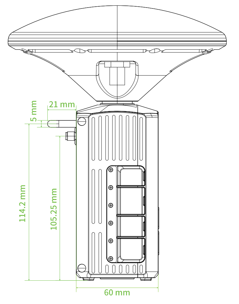
USR20-G Installation Diagram