1.2.2 USL10 Video Link
USL10-A Airborne Unit
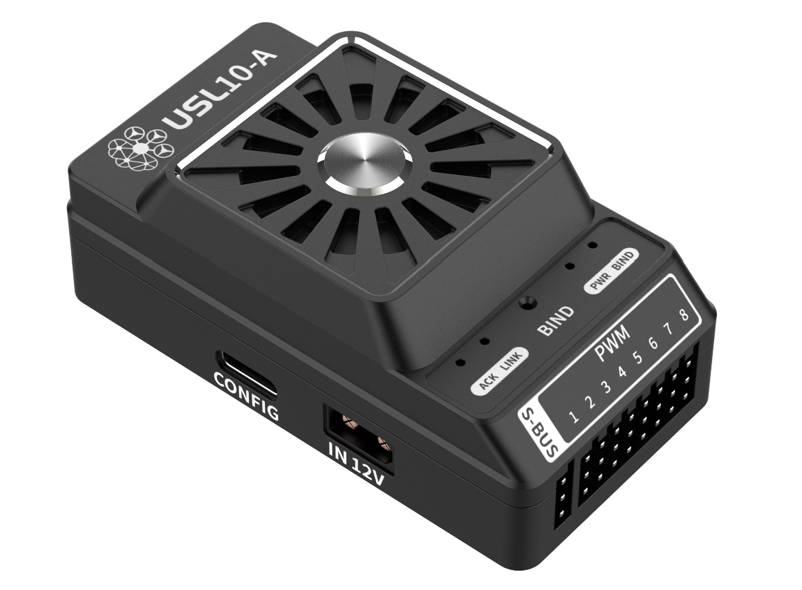
Product Description
The UAV onboard integrated video and data transmission core component can real-time encode and wirelessly transmit the onboard camera HD video stream, flight controller telemetry, and sensor data, while receiving ground station control commands and forwarding them to the flight controller and mission equipment. Low-latency, high anti-interference wireless transmission architecture supports long-distance communication and adaptive link adjustment.
Specifications
| Parameter | Specification |
|---|---|
| Supply Voltage | 12V |
| Power Consumption | 3W |
| Maximum Transmit Power | 28dBm @2.4G / 26dBm @5.8G |
| Channel Bandwidth | 1.25/2.5/5/10/20/40 MHz |
| Modulation Mode | BPSK/QPSK/16QAM/64QAM/256QAM |
| Channel Selection | Adaptive frequency hopping |
| Transmission Distance | 10km |
| Air Data Rate | 200Kbps ~ 160Mbps |
| Encryption Algorithm | AES/DES/3DES for Hardware |
| Frequency Band | 2.4~2.48GHz / 5.15~5.87GHz |
| Antenna Interface | MMCX × 2 |
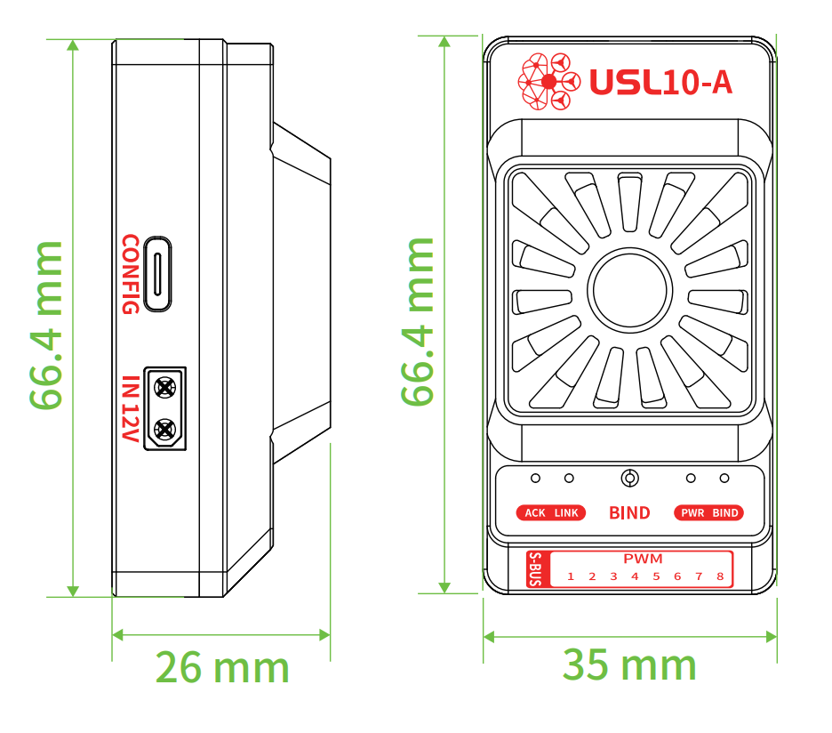
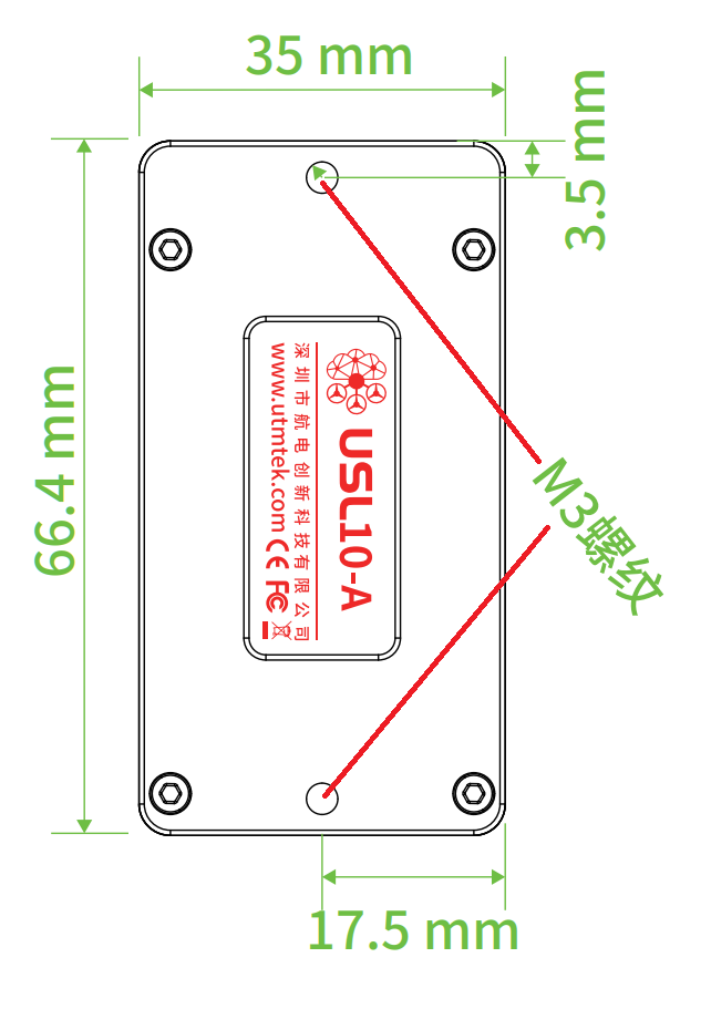
| Dimensions | 66.4mm × 35mm × 26mm |
| Weight | 55g |
| Operating Temperature | -20 ~ 80°C |
Interface Definition
| Interface Name | Function Description | Interface Type |
|---|---|---|
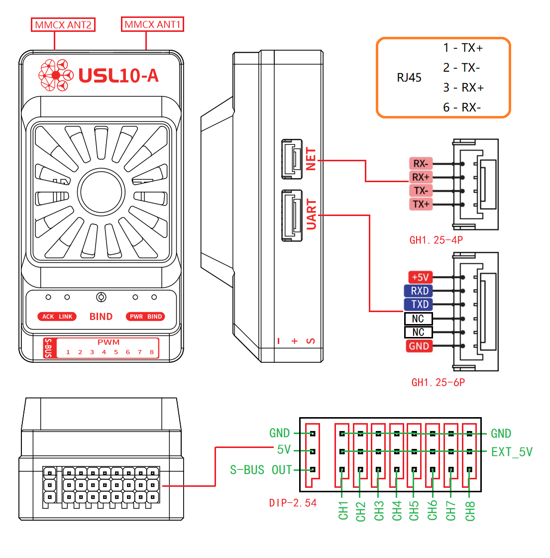
| IN 12V | Power input | XT30 |
| CONFIG | Configuration interface | Type-C |
| NET | Network interface | GH1.25-4P |
| UART | Serial communication | GH1.25-6P |
| BIND | Pairing button | - |
| S-BUS | Remote control signal | - |
| PWM1~8 | PWM output | - |
Status LEDs
| LED | Description |
|---|---|
| LINK | Link connection status |
| PWR | Power indicator |
| BIND | Pairing status |
Product Drawings
USL10-A Interface Diagram
USL10-A Dimensions Diagram
USL10-A Installation Diagram
USL10-G Ground Unit
Product Description
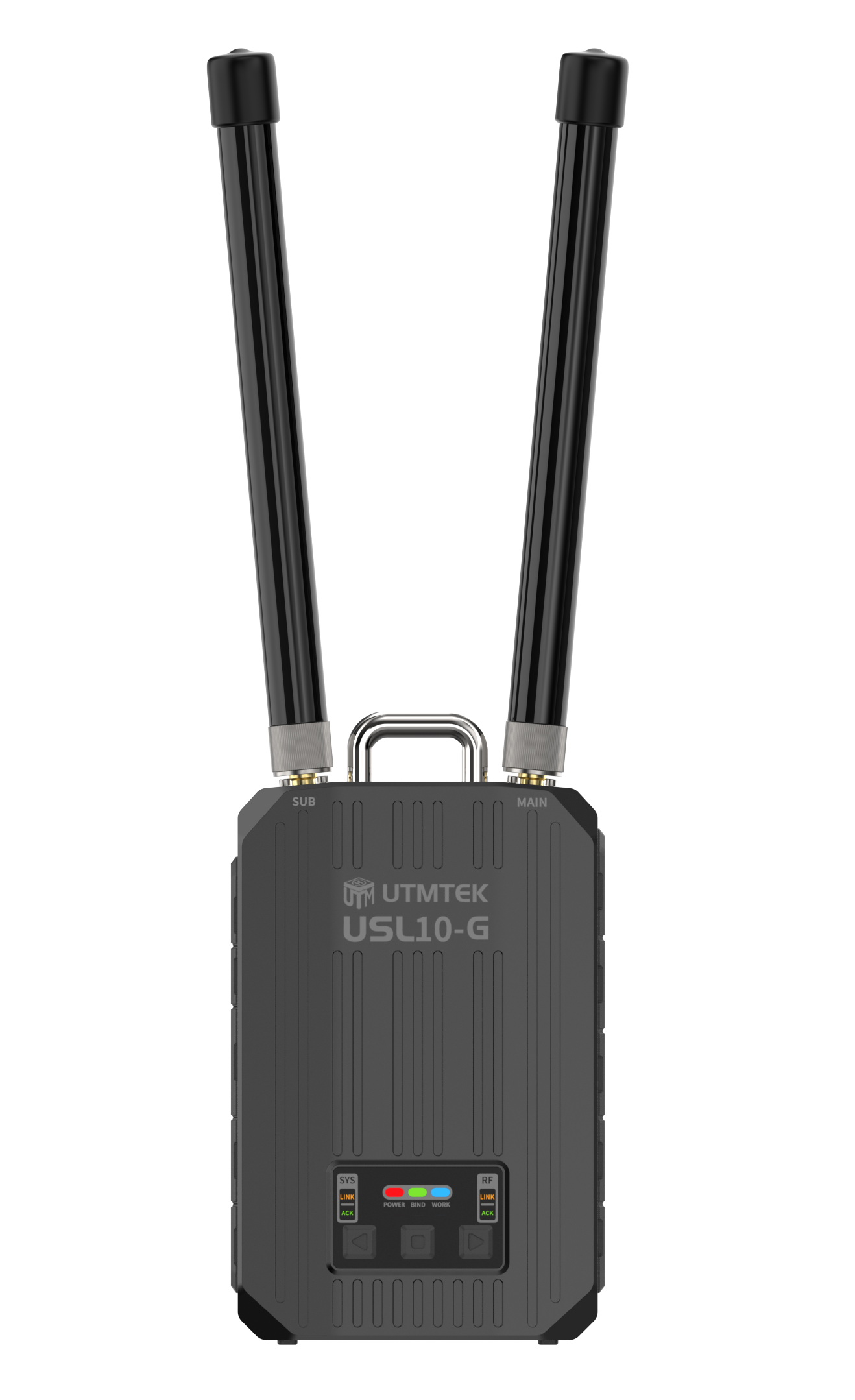
The ground wireless communication core equipment used with the airborne unit, responsible for real-time receiving of UAV HD video images, flight controller telemetry, and sensor status data, and transmitting ground station control commands and route planning uplink to the airborne unit.
Specifications
| Parameter | Specification |
|---|---|
| Supply Voltage | 12 ~ 25V |
| Power Consumption | 3W |
| Maximum Transmit Power | 28dBm @2.4G / 26dBm @5.8G |
| Channel Bandwidth | 1.25/2.5/5/10/20/40 MHz |
| Modulation Mode | BPSK/QPSK/16QAM/64QAM/256QAM |
| Channel Selection | Adaptive frequency hopping |
| Transmission Distance | 10km |
| Air Data Rate | 200Kbps ~ 160Mbps |
| Encryption Algorithm | AES/DES/3DES for Hardware |
| Frequency Band | 2.4~2.48GHz / 5.15~5.87GHz |
| Antenna Interface | SMA female inner thread × 2 |
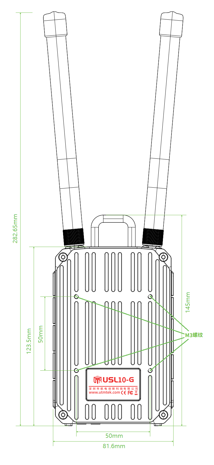
| Dimensions | 145mm × 81.6mm × 33.1mm |
| Weight with Antenna | 388g |
| Operating Temperature | -20 ~ 80°C |
Interface Definition
| Interface Name | Function Description | Interface Type |
|---|---|---|
| IN 12~25V | Power input | XT30 |
| USB | USB interface | USB-A |
| HDMI | HDMI input | HDMI |
| AV | AV input | 3.5mm TRRS |
| TYPE-C | Debug/Configuration | Type-C |
| UART | Serial communication | MR30 |
| NET1 | Gigabit network port 1 | RJ45 |
| NET2 | Gigabit network port 2 | RJ45 |
| CHANGE | Output toggle switch | - |
| TF | TF card slot | MicroSD |
| MAIN/SUR | Antenna interface | SMA |
| BIND | Pairing button | - |
| FEEL | Tactile feedback | - |
Product Drawings
USL10-G Dimensions Diagram
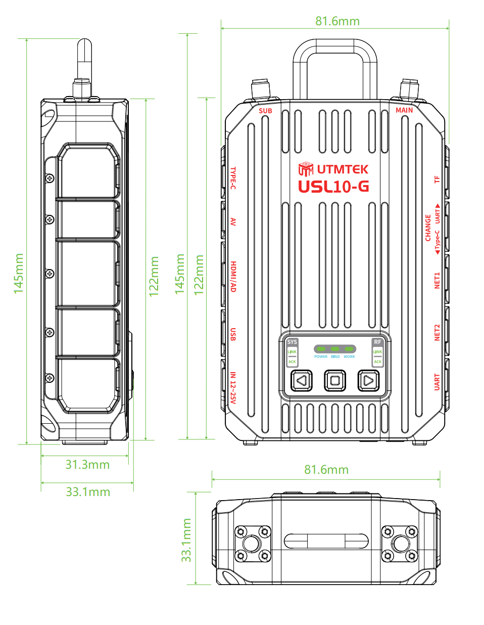
USL10-G Installation Diagram