PX4_ROS2_uXRCE-DDS
Micro XRCE-DDS replaces the Fast-RTPS Bridge used in PX4 v1.13. If you were previously using the Fast-RTPS Bridge, please follow the migration guide.
PX4 uses the uXRCE-DDS middleware, which allows uORB messages to be published and subscribed to on the companion computer , just like ROS 2 topics. This enables fast and reliable integration between PX4 and ROS 2, and makes it easier for ROS 2 applications to get drone information and send commands.
The following guide describes the architecture and various options for setting up clients and proxies. It specifically covers the options that are most important to PX4 users.
Communication
The uXRCE-DDS middleware consists of a client running on PX4 and an agent running on a companion computer, which exchange bidirectional data over a serial or UDP link. The agent acts as a proxy for the client, enabling it to publish and subscribe to topics in the global DDS data space.

In order to share a PX4 uORB topic over a DDS network, you need to run the uXRCE-DDS Client on the PX4 and connect it to the uXRCE-DDS Agent running on a companion computer.
Using a serial port
The AI UART2 of the RDK X5 Module and /dev/ttyS2 the FC UART5 of the Pixhawk 6X /dev/ttyS4 can communicate through the internal serial port connection, as shown in the figure: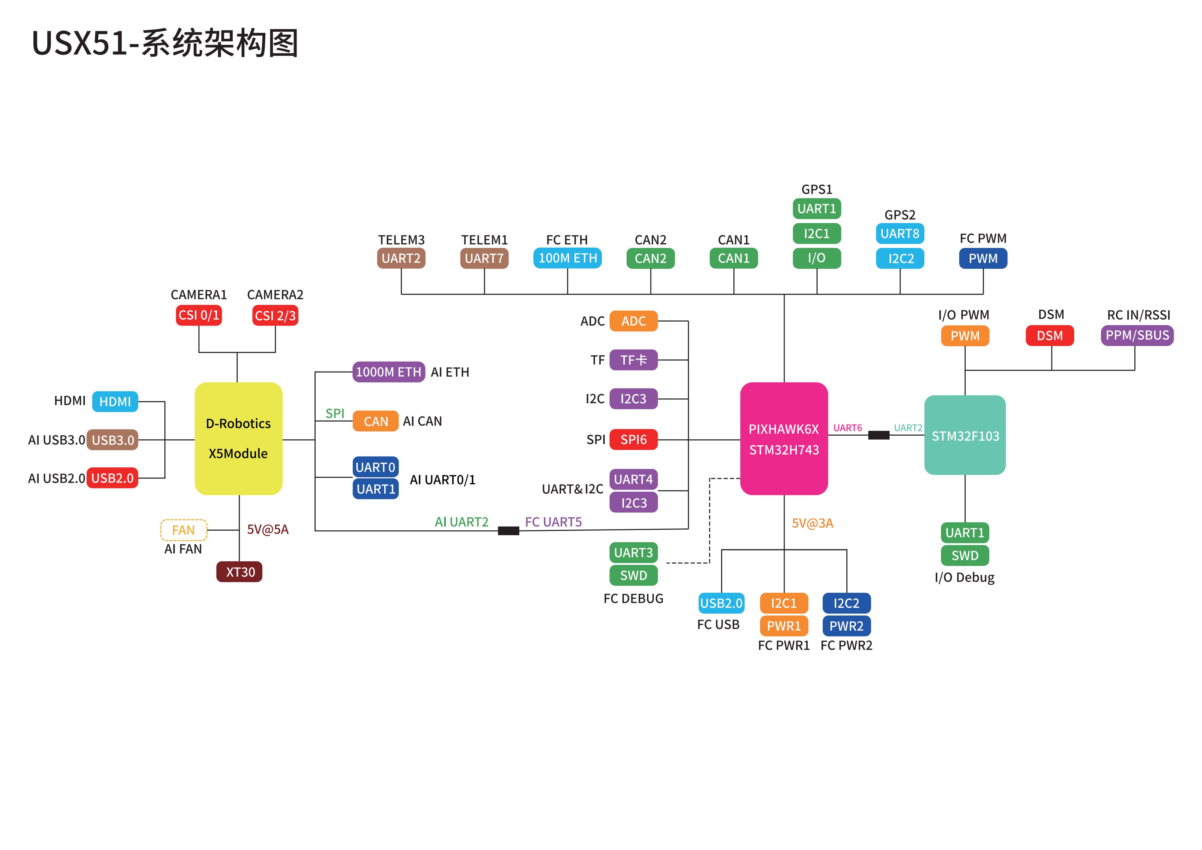
The ROS 2 guide and the uXRCE-DDS page cover options for setting up uXRCE-DDS and ROS. This tutorial uses ROS 2 "Humble" and covers the specific setup using the RDK X5 Module.
Pixhawk/PX4
Next, we TELEM2 set up ROS 2 instead of MAVLink. We do this by changing the parameters in QGroundControl. QGroundControl can be connected via USB or use TELEM1 the telemetry radio it is connected to.
The configuration steps are as follows:
- Connect your Pixhawk to your laptop using the USB cable and open QGroundControl if it is not already connected.
- Check/change the following parameters in QGroundControl:
MAV_1_CONFIG = 0 and UXRCE_DDS_CFG = 102 disable MAVLink over TELEM2 and enable the uXRCE-DDS client over TELEM2, respectively.
MAV_1_CONFIG = 0 (Disabled)
UXRCE_DDS_CFG = 102 (TELEM2)
SER_TEL2_BAUD = 921600SER_TEL2_BAUDThis setting sets the data rate for the communication link. You can similarly configure the connection with SER_TEL2_BAUD using SER_TEL2_BAUDMAV_1_CONFIGorMAV_0_CONFIGSER_TEL2_BAUD_CFGTELEM1. If the SER_TEL2_BAUD parameter is missing, enable it by setting MAV_1_CONFIG = TELEM2 and then resetting it using the above steps. - The PX4 uxrce_dds_client is generated at build time and included by default in the PX4 firmware. Check that the uxrce_dds_client module is running. You can do this by running the following command in the QGroundControl MAVLink console:
uxrce_dds_client status
ROS
The steps to set up ROS 2 and Micro XRCE-DDS Agent on the RDK X5 Module are as follows:
- Install ROS 2 Humble according to the official tutorial.
- Install git using the RDK X5 Module terminal
sudo apt install git - Install ROS2 compilation tool colcon
sudo apt update
sudo apt install python3-colcon-common-extensions - Install Micro XRCE-DDS Agent See uXRCE-DDS > Micro XRCE-DDS Agent Installation for alternative methods of installing the agent.
- Enable UART2 serial port and edit /boot/config.txt file, add dtparam=uart2=on
sudo nano /boot/config.txt - Start the agent in the RDK X5 Module terminal:
Note how we use the serial port we set up previously and the same baud rate as the PX4.
sudo MicroXRCEAgent serial --dev /dev/ttyS2 -b 921600
Now that both the agent and client are running, you should see activity in both the MAVLink console and the RDK X5 Module terminal.
When PX4 is up and running, the PX4 terminal displays the output from the NuttShell/PX4 system console. Once the agent is connected, the output should include INFO a message about creating the data writer:
...
INFO  [uxrce_dds_client] synchronized with time offset 1675929429203524us
INFO  [uxrce_dds_client] successfully created rt/fmu/out/failsafe_flags data writer, topic id: 83
INFO  [uxrce_dds_client] successfully created rt/fmu/out/sensor_combined data writer, topic id: 168
INFO  [uxrce_dds_client] successfully created rt/fmu/out/timesync_status data writer, topic id: 188
...
The Micro XRCE-DDS Agent terminal on the RDK X5 Module should also start showing output as an equivalent topic is created in the DDS network:
...
[1675929445.268957] info     | ProxyClient.cpp    | create_publisher         | publisher created      | client_key: 0x00000001, publisher_id: 0x0DA(3), participant_id: 0x001(1)
[1675929445.269521] info     | ProxyClient.cpp    | create_datawriter        | datawriter created     | client_key: 0x00000001, datawriter_id: 0x0DA(5), publisher_id: 0x0DA(3)
[1675929445.270412] info     | ProxyClient.cpp    | create_topic             | topic created          | client_key: 0x00000001, topic_id: 0x0DF(2), participant_id: 0x001(1)
...
You can view the available themes on the RDK X5 Module using the following command:
source /opt/ros/humble/setup.bash
ros2 topic list
The following topics
...
/fmu/in/obstacle_distance
/fmu/in/offboard_control_mode
/fmu/in/onboard_computer_status
/fmu/in/register_ext_component_request
/fmu/in/sensor_optical_flow
/fmu/in/telemetry_status
/fmu/in/trajectory_setpoint
/fmu/in/unregister_ext_component
/fmu/in/vehicle_attitude_setpoint
/fmu/in/vehicle_command
/fmu/in/vehicle_command_mode_executor
/fmu/in/vehicle_mocap_odometry
/fmu/in/vehicle_rates_setpoint
/fmu/in/vehicle_thrust_setpoint
/fmu/in/vehicle_torque_setpoint
/fmu/in/vehicle_trajectory_bezier
/fmu/in/vehicle_trajectory_waypoint
/fmu/in/vehicle_visual_odometry
/fmu/out/estimator_status_flags
/fmu/out/failsafe_flags
/fmu/out/manual_control_setpoint
/fmu/out/position_setpoint_triplet
/fmu/out/sensor_combined
/fmu/out/timesync_status
/fmu/out/vehicle_attitude
/fmu/out/vehicle_control_mode
...
Once connected, refer to the ROS 2 Guide for more information on using PX4 with ROS 2.
Using Ethernet
Start
The agent is used to connect to the client over a specific channel, such as UDP or a serial connection. Channel settings are specified using command-line options when the agent is started. These settings are documented in the eProsima User Guide: Micro XRCE-DDS Agent > Agent CLI. Note that the agent supports multiple channel options, but PX4 only supports UDP and serial connections.
For example, the PX4 emulator runs the uXRCE-DDS client over UDP on port 8888, so to connect to the emulator you can start the proxy with:
MicroXRCEAgent udp4 -p 8888
Start the
All firmware and simulators include the uXRCE-DDS client module ( uxrce_dds_client ) by default. This module must be enabled with the appropriate settings for the channel you wish to use to communicate with the agent.
Configuration can be done using the UXRCE-DDS parameters:
- UXRCE_DDS_CFG: Set the port to connect to, for example
TELEM2,,EthernetorWifi. - If using an Ethernet connection:
- UXRCE_DDS_PRT: Used to specify the proxy UDP listening port. The default value is
8888. - UXRCE_DDS_AG_IP: Specifies the IP address of the proxy.
int32Since PX4 does not support string parameters, the IP address must be provided in string format. The default2130706433value127.0.0.1is localhost. You can use Tools/convert_ip.py to convert between formats:- To get
int32the IP version in decimal dot notation, use the following command:python3 ./PX4-Autopilot/Tools/convert_ip.py <the IP address in decimal dot notation> - To get the IP address in dot-decimal notation from the version
int32:python3 ./PX4-Autopilot/Tools/convert_ip.py -r <the IP address in int32 notation>
- To get
- UXRCE_DDS_PRT: Used to specify the proxy UDP listening port. The default value is
- Some setups may also require setting these parameters:
- UXRCE_DDS_KEY: uXRCE-DDS key. If you are using a multi-client single-agent configuration, each client should have a unique, non-zero key. This is especially important for multi-vehicle simulations, where all clients connect to the same agent via UDP. (See the official eprosima documentation.
uxr_init_session) - UXRCE_DDS_DOM_ID: The DDS domain ID. This provides logical isolation between DDS networks and can be used to distinguish clients on different networks. By default, ROS 2 runs on ID 0.
- UXRCE_DDS_PTCFG: uXRCE-DDS participant configuration. It allows to restrict visibility of DDS topics to localhost only and use user-defined participant configuration files stored on the broker side.
- UXRCE_DDS_SYNCT: Bridge time synchronization enabled. The uXRCE-DDS client module can synchronize the timestamps of messages exchanged over the bridge. This is the default configuration. In some cases, such as during simulation, this feature may be disabled.
- UXRCE_DDS_KEY: uXRCE-DDS key. If you are using a multi-client single-agent configuration, each client should have a unique, non-zero key. This is especially important for multi-vehicle simulations, where all clients connect to the same agent via UDP. (See the official eprosima documentation.
After the settings are completed, you may need to restart PX4 for the parameters to take effect. These parameters will be retained after subsequent restarts.
You can also start uxrce_dds_client from the command line . This can be called as part of system startup or through the MAVLink Shell (or the system console). This method is useful when you need to set a custom client namespace, as no arguments are given for this. For example, the following command can be used to connect to a remote host via Ethernet 192.168.0.100:8888 and set the client namespace to /drone/.
uxrce_dds_client start -t udp -p 8888 -h 192.168.0.100 -n drone
Option -p or -h used to bypass UXRCE_DDS_PRT and UXRCE_DDS_AG_IP.
Launching the
The simulator startup logic ( init.d-posix/rcS ) uses the client startup command for single-vehicle and multi-vehicle simulations, which sets the appropriate instance ID and DDS namespace. By default, the client is started on the localhost UDP port 8888 without any additional namespace.
Environment variables are provided to override certain UXRCE-DDS parameters. These variables allow users to create custom startup files for their simulations:
PX4_UXRCE_DDS_NS: Use this to specify the topic namespace ).ROS_DOMAIN_ID: Use this to replace UXRCE_DDS_DOM_ID.PX4_UXRCE_DDS_PORT: Use it to replace UXRCE_DDS_PRT.
For example, the following command can be used to start a Gazebo simulation running the che client on the DDS domain 3, port, and topic namespace .9999 drone
ROS_DOMAIN_ID=3 PX4_UXRCE_DDS_PORT=9999 PX4_UXRCE_DDS_NS=drone make px4_sitl gz_x500
The broker and client are now running and they should connect.
When PX4 is up and running, the PX4 terminal displays the output from the NuttShell/PX4 system console. Once the agent is connected, the output should include INFO a message about creating the data writer:
...
INFO  [uxrce_dds_client] synchronized with time offset 1675929429203524us
INFO  [uxrce_dds_client] successfully created rt/fmu/out/failsafe_flags data writer, topic id: 83
INFO  [uxrce_dds_client] successfully created rt/fmu/out/sensor_combined data writer, topic id: 168
INFO  [uxrce_dds_client] successfully created rt/fmu/out/timesync_status data writer, topic id: 188
...
The Micro XRCE-DDS Agent terminal should also begin displaying output as an equivalent topic is created in the DDS network:
...
[1675929445.268957] info     | ProxyClient.cpp    | create_publisher         | publisher created      | client_key: 0x00000001, publisher_id: 0x0DA(3), participant_id: 0x001(1)
[1675929445.269521] info     | ProxyClient.cpp    | create_datawriter        | datawriter created     | client_key: 0x00000001, datawriter_id: 0x0DA(5), publisher_id: 0x0DA(3)
[1675929445.270412] info     | ProxyClient.cpp    | create_topic             | topic created          | client_key: 0x00000001, topic_id: 0x0DF(2), participant_id: 0x001(1)
...
Communication Example
ROS2 wanting to subscribe to or publish to PX4 messages needs a px4_msgs that matches the uORB message definition used to create the PX4 uXRCE-DDS Client so that the messages can be interpreted.
When building PX4 officially, the code generator compiles support for a subset of uORB topics in /src/modules/uxrce_dds_client/dds_topics.yaml into uxrce_dds_client using the uORB message definitions in the source tree PX4-Autopilot/msg.
A PX4 master or release build automatically exports a set of uORB message definitions from the build to the associated branch in PX4/px4_msgs.
ROS 2 applications need to be built in a workspace that contains the same message definitions used to create the uXRCE-DDS client module in the PX4 firmware. You can add these message definitions to your ROS 2 workspace by cloning the interface package PX4/px4_msgs into your workspace and switching to the corresponding branch. Note that all message-related code generation is handled by ROS 2.
px4_ros_com
https://docs.px4.io/main/en/ros2/offboard_control.html
https://github.com/PX4/px4_ros_com.git
px4-ros2-interface-lib
https://docs.px4.io/main/en/ros2/px4_ros2_interface_lib.html
https://github.com/Auterion/px4-ros2-interface-lib
More
Please refer to the official PX4 documentation